The IOWAY firmware
Programming the IOWAY
The IOWAY consists of 2 elements:
- Olimex ESP32-PoE
- Link7 (DASH7 modem)
On this page we list instructions on how to create custom applications for the Olimex ESP32-PoE and link7 and how they can be programmed using the serial-to-USB converter.
windows drivers
To program the IOWAY, the device will need to be connected to a computer. This connection is handled by the on board serial-to-USB converter. A windows PC will require a driver to be installed for this chip. This driver can be downloaded from the USB drivers section on Olimex ESP32-PoE.
Link7 (DASH7 Modem)
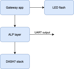
Default firmware architecture
Writing custom firmware
In the Sub-IoT-Stack submodule, there’s a folder ‘apps’ containing a ‘gateway’ folder. This folder represents the current application running on the DASH7 gateway. This application already shows you how to handle message that are arriving, how to change the state of the LED and how to handle a button press.
Flashing custom firmware
When your firmware is fully built (build instructions) without any errors, the firmware-files should be available in the build folder.
Make sure the IOWAY gateway is plugged in through the micro USB connector (located on the Olimex ESP32-board) to your computer.
Flashing the firmware is done through the STM32CubeProgrammer.
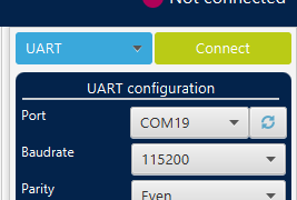
Open up the programmer and select ‘UART’ as the source:
Now activate the bootloader on the IOWAY gateway by pressing the ‘prog’ button of the Link7. It is the button located towards the middle of the device close the antenna connector.
Click the refresh button next to the port. Your device should pop-up as one of the options. Select it and press the ‘Connect’ button.
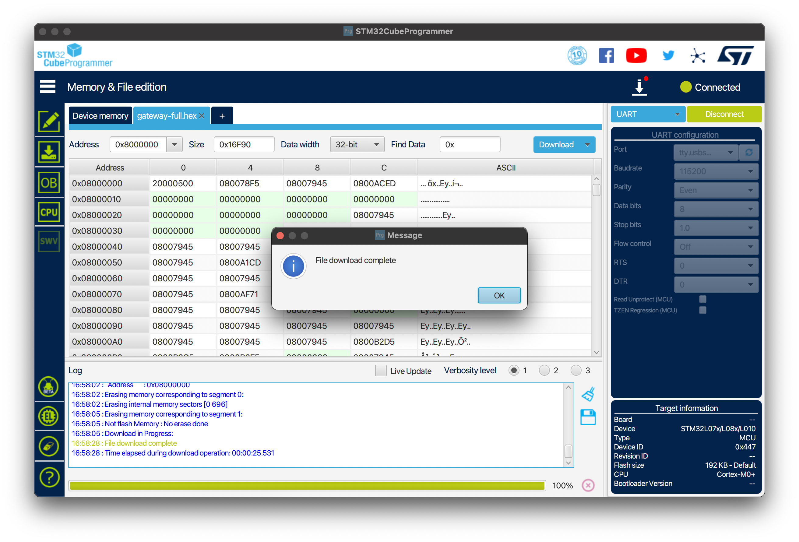
Now press the ‘Open file’ button and select your firmware file (/your/path/LiQuiBit/build/Link7-gateway/apps/gateway/gateway-full.hex). Then select ‘Download’ and it will start flashing the device. When it’s done, a pop-up will show ‘File download complete’.
Wi-Fi Modem (ESP32)
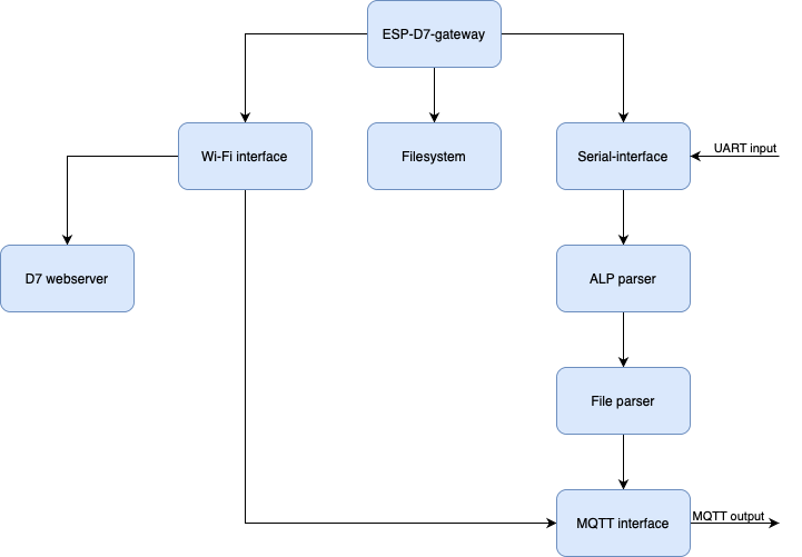
Default firmware architecture
Writing custom firmware
Development is done in the Arduino IDE.
All blocks are written so they could be easily swapped out by others, there are no connections between the blocks that aren’t necessary.
Flashing custom firmware
In the Arduino IDE, first add an Additional Boards Manager URL: https://raw.githubusercontent.com/espressif/arduino-esp32/gh-pages/package_esp32_dev_index.json
Our code currently depends on the following libraries that can be installed through the Library Manager:
| Library | Known working version |
|---|---|
| PubSubClient by Nick O’Leary | 2.8.0 |
| CRC by Rob Tillaart | 0.3.2 |
Then, configure the following settings:
| Setting | Value |
|---|---|
| Board | OLIMEX ESP32-PoE |
| Upload speed | 921600 |
| Port | /Your/USB/Port |
Once this is configured, press the ‘Upload’ button. This should compile and flash your sketch to the board.
...
Sketch uses 755958 bytes (57%) of program storage space. Maximum is 1310720 bytes.
Global variables use 42556 bytes (12%) of dynamic memory, leaving 285124 bytes for local variables. Maximum is 327680 bytes.
esptool.py v3.3
Serial port /dev/cu.usbserial-1330
Connecting....
Chip is ESP32-C3 (revision 3)
Features: Wi-Fi
Crystal is 40MHz
...
Writing at 0x000c4ae9... (96 %)
Writing at 0x000cab43... (100 %)
Wrote 788384 bytes (473373 compressed) at 0x00010000 in 12.3 seconds (effective 512.4 kbit/s)...
Hash of data verified.

Leaving...
Hard resetting via RTS pin...
The program should now be running on the ESP32!