Pinout
Push7
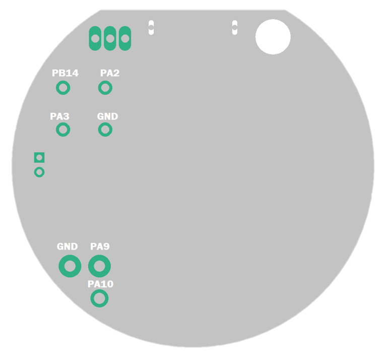
The orientation of the board is seen as the Micro-USB being at the top.

| Location | Pin | Functions |
|---|---|---|
| J2, bottom pin | PA10 | Interrupt, I2C1_SDA, USART1_RX |
| J2, left pin | GND | |
| J2, right, top pin | PA9 | Interrupt, I2C1_SCL, USART1_TX |
| PIR, left, top pin | PB14 | Interrupt, |
| PIR, right, top pin | PA2 | ADC2, USART2_TX |
| PIR, left, bottom pin | PA3 | Interrupt, ADC3, USART2_RX |
| PIR, right, bottom pin | GND |
Note: Keep in mind when using I2C on these pins that the internal senors are utilizing the same bus with different GPIO pins (PB8-I2C1_SCL/PB9-I2C1_SDA). Trying to use the same bus on different pins at the same time might cause issues during initialization.
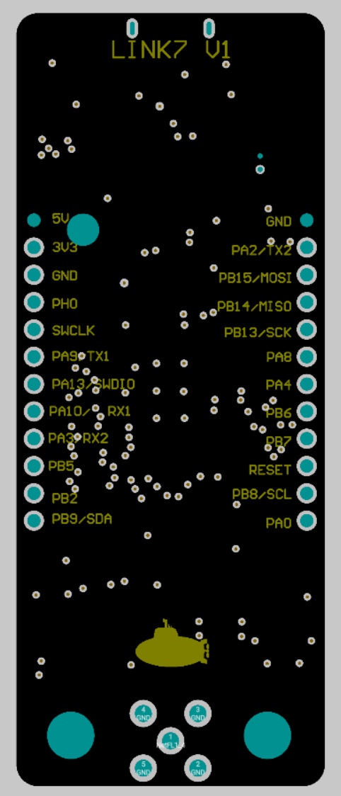
LINK7
This is a view from the bottom of the board. The pin names are also displayed on the silk screen of the board.
